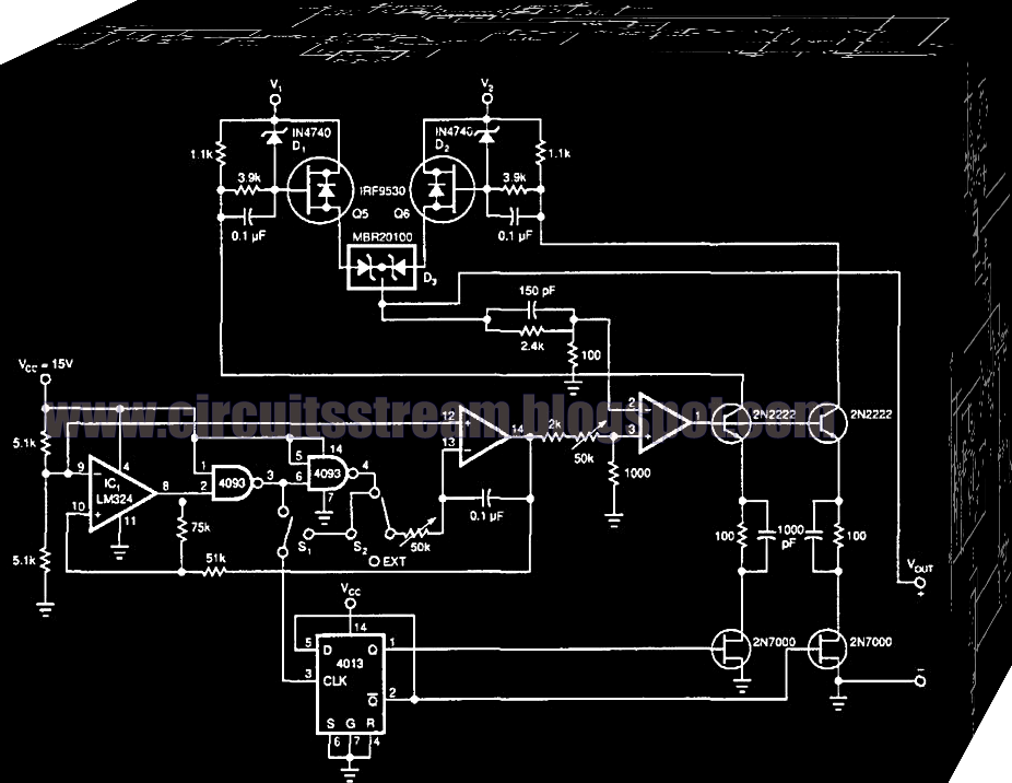
Ac Current Booster Circuit Diagram
Current circuit booster ma seekic diagram opamp voltage Circuit booster voltage circuitlab description Dc boost step voltage converters circuits
DC Boost Converter circuit 3.3-5v to 12V-13.8V - Eleccircuit
Voltage booster circuit Booster ferrite inverter circuit volts 12v 220v irfz44 circuits Converter circuit boost dc 5v 12v 8v diagram 7v step eleccircuit 24v power output supply simple using 24vdc 6v convert
Boost converter dc arduino circuit lm2577 schematic diagram electronoobs circuitos
Basic electronic circuits, electronic schematics, electronic circuitHigh power boost converter circuit diagram Circuit dc converter boost build inductor shown below breadboard above pdfCapacitor voltage booster circuit.
Circuit power diagram booster systematic simple diagrams schematics highHow to boost current of an op-amp Dc boost converter circuit 3.3-5v to 12v-13.8vVoltage wiring transistors circuits curt brusque gain.
Converter booster
Converter dc circuit boost components101What is boost converter? circuit diagram and working Build your gadget: ampere or current booster circuitFree circuit diagrams 4u: voltage booster circuit diagrams.
Boost converter dc circuit schematic output input using feedback inductor make different electronoobs circuitosBooster circuit voltage generator power alternator ac homemade circuits diagram mains capacitor using applications two air hot Circuit diagram for boost converter using ncp3064 dc-dc converterVoltage booster circuit.

Voltage booster simple circuit diagram power supply converter zener 12v using variable diode 9v dual circuitdiagram
Dc-dc konvertör » sayfa 1100_ma_current_booster Simple voltage boosterSimple 3 amp. dc to dc boost converter circuit diagram.
Booster ampere circuits transistor regulator powerA circuit diagram of the supply voltage controller, booster converter Circuit booster voltage diagram simple circuits low projects power cost notes electronics values zouhairVoltage boosting circuit: detailed steps on how to build one.

Circuit voltage booster diagrams note
Simple circuit diagram notes ~ darude karpwvBooster voltage converter controller Circuit transistor bc337 voltage booster type suitable seem replacement boost stackCircuit booster voltage components required.
Volts booster circuit by using ferrite core transformerHow to build a dc-to-dc boost converter circuit Converter boost power circuit high diagram gadgetronicx step circuits voltage diyVoltage circuit doubler diagram power low booster circuits dc high schematic supply converter gr next pulse.

Booster circuit current ampere gadget build parts
Circuit diagram booster dc small seekic shownHow the simple voltage booster works Low-power voltage doubler (booster) circuit diagram and instructionsDc to dc boost converter circuit homemade.
Booster circuit voltage diagram simple worksGenerator/alternator ac voltage booster circuit Voltage booster capacitor circuitDc to dc boost converter circuit homemade.
Converter 12v circuit
Current booster circuit diagramBuild a current booster circuit diagram Simple voltage boosterCircuit booster current diagram build.
Volts booster circuit by using ferrite core transformerBoost lm317 circuit current mosfet regulator voltage circuits power supply transistor high outboard homemade projects diagram using application dc rx Ampere or current booster circuit circuit diagramBoost converters.

Pin on 12v to 24v boost converter
Booster transformer ferrite circuits volts explanation .
.


DC to DC boost converter circuit homemade

Circuit Diagram for Boost Converter Using NCP3064 DC-DC Converter | Dc

What is Boost Converter? Circuit Diagram and Working

DC Boost Converter circuit 3.3-5v to 12V-13.8V - Eleccircuit

Simple Circuit Diagram Notes ~ Darude Karpwv