Ne555 Pwm Circuit Diagram
Amp ne5532 circuit headphone diagram amplifier op power ic forum simple caps schematic eevblog output inputoutput beginners wiring diagrams input Circuit diagram of pwm using 555 555 pwm mosfet diagram
555 Pwm Circuit Diagram
Simple pwm circuit diagram Design of ne555 circuits simulation || ne555 circuits in astable mode Pwm ne555
12v ne555 pwm controller under $3
Pwm 555 analog signal timer requirement50 amp pwm circuit diagram Make this pwm based dc motor speed controller circuitPwm 555 circuit dimmer led mosfet light signal schematic power applications supply sparkfun current high ne555 timer 12v arduino using.
Ne5532 power amplifier circuit diagramOperational amplifier Pwm with ne555Pulse modulation pwm circuitbasics.

Pwm ne555 circuit
Pwm circuit diagram using 555Motor control circuit composed of ne555 Pwm dc motor controller using ne555Bmw m5 or m3, pwm controller ic.
Dc motor control pwm with 555Pwm circuit diagram using 555 A simple 555 pwm circuit with motor exampleNe555 adjustable pwm circuit.

555 pwm ltspice timer mathscinotes implementation
Ne555 pwm 12v circuit besuchenPwm circuit diagram using 555 Schematic ne555 motors controller working power big circuitlab created usingPulse width modulation circuit.
Pwm ne555 12v pic circuits between two circuit signals difference schematicHow to build a pulse width modulation signal generator Circuit ne555 motor control diagram composed seekic ic frequencyThe ne555 timing circuit of ±15v power supply.

Motor circuit dc speed controller pwm control simple circuits diagram make based ic 24vdc schematic mosfet 555 high current potentiometer
Pwm ne555 timer ic circuit but oldschool p1 adjusted dynamic staticFalca de moarte atârna analgezic ne555 pwm generator fabulă rochie de A low cost pwm dimmer using ne555 and mosfet with diy aluminium casePwm dc motor speed control using ne555.
Pwm motor current control ic 555 limiter circuits circuit schematic speed mosfet diagram power limiting gr nextPwm ne555 mosfet dimmer instructables circuits Analysis of 555-based pwm circuitPwm – electronic circuit diagram.

555 pwm circuit diagram
Pwm dc motor speed controller schematicPwm 555 motor circuit dc control power supply speed 90vdc circuits timer astable fan battery circuito mosfet velocidad diagrama circuitos 555 pwm circuit diagram.
.
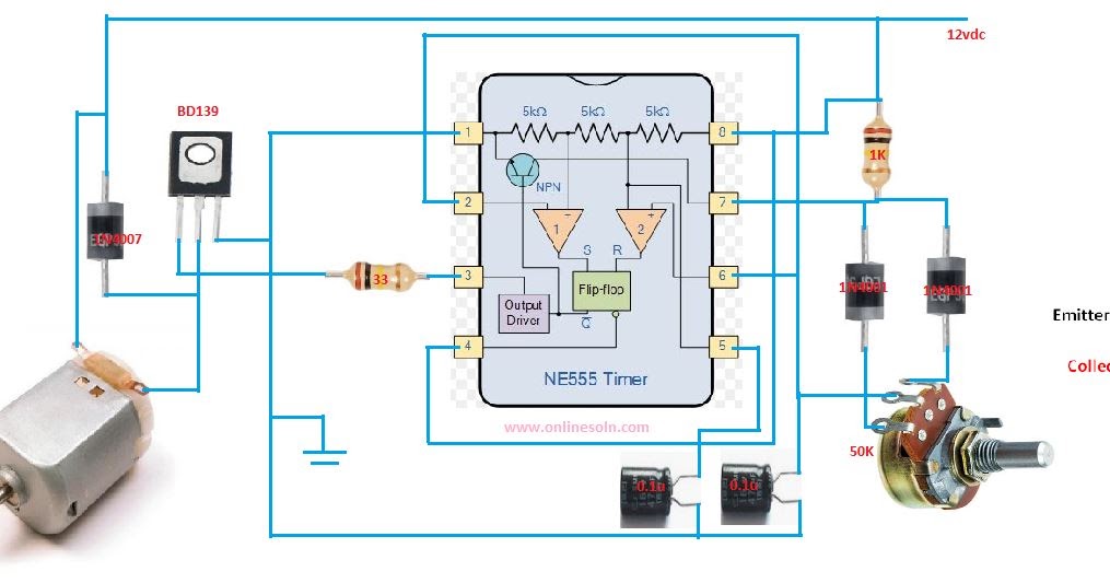
PWM DC MOTOR SPEED CONTROL USING NE555 | CIRCUIT DIAGRAM

microcontroller - Difference between two 12V PWM signals/circuits (PIC

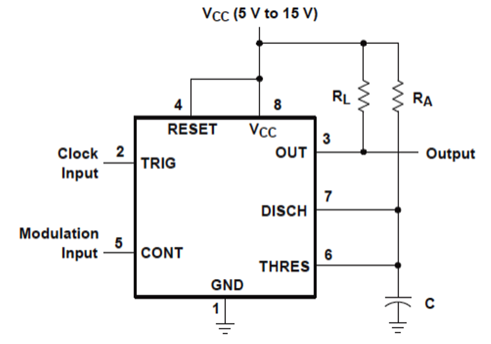
Design of NE555 Circuits Simulation || NE555 Circuits in Astable Mode

Analysis of 555-Based PWM Circuit | Math Encounters Blog

pwm circuit diagram using 555 - IOT Wiring Diagram

pwm circuit diagram using 555 - IOT Wiring Diagram

How to Build a Pulse Width Modulation Signal Generator - Circuit Basics